The ball bearing motor mystery 2022
Project team
Honours students
- Xinyao Feng
Supervisors
General project description
The ball bearing motor is a mystery because to this day as no engineer knows how it works! No one understands the physical principle at all. Your job is to do some experiments to investigate this motor and why it is that it rotates. Understanding the principle is important. It may not be useful for large motors, but it may be interesting for micromotors and micropumps that have numerous applications.
Abstract
The mystery of the ball-bearing motor is based on the Huber effect, a theory named in memory of J. Huber [1]. There’s been no conclusive experimental evidence to support this effect since then. In 1959, J. Huber found additional rotational force on the conductive wheel pair when the current was supplied and pass through the track [1]. Whether direct current (DC) or alternating current (AC) is used, additional forces that accelerate the wheels can be observed. Milroy first described the ball bearing motor based on the Huber effect [2]. It is composed of a metal shaft with one ball bearing is installed at both ends, as shown in Figure 1.1 [3]. Give an initial beginning torque to the shaft when AC or DC power is applied to the system, and the system will continue to rotate in the starting direction. The motor can rotate in any direction freely.

Aim
According to previous research, many theories have been put forward, but no conclusive experimental evidence exists. Therefore, this project aims to study the physical mechanism behind the ball-bearing motor. This project will build physical models using relatively small size ball bearings. The small sizing can reduce the working current. Then, distilled water will be applied to the system to reduce the overheating and self-destruction effect. In addition, the liquid metal will be used in a modified system to reduce the system friction force. The Arduino board, LCD scream, speed encoder module and load cell will be used to collect data, which will be used to establish the relationship between angular velocity and torque. Meanwhile, simulation experiments using the software COMSOL will be performed in parallel with the physical experiments. It is used to perform the experiment in ideal cases and support the physical experiment results through software calculations.
Background
None of the existing hypotheses about the physical mechanism behind the Huber effect can contradict other hypotheses or summarize conclusions. Three representative assumptions are the electromagnetic effect, thermal expansion, and plasma discharge.
Electromagnetic effect
Grunberg initially hypothesized that the Milroy motor phenomena were caused by an electromagnetic effect. [3]. Each ball in the bearing has the properties of magnetic field B0 and volume current density J0. Because current passes between the contacts on the inner and outer rings, it is assumed that the ball’s angular velocity is ω. The primary magnetic field B0 will be generated, and the secondary volume current density J1 will be generated according to the movement of B0. The process repeats as the ball rotates, which leads to the redistribution of associated magnetic field B1 and electric field E1 and charge. The primary torque source results from the interaction between B1, J0 and B0, J1. Grunberg’s research shows that torque and vector ω. The direction is consistent, so the motor will produce rotating torque only when running, and there is no starting torque. At the same time, he proposed that the speed is directly proportional to the current square based on the analysis of static Maxwell equations.
T = k * ω* I^2 (1)
where I = sqrt (a + b * ω) (2)
However, Weennink proved that these relations are incorrect in algebra [4]. Further on, Moyssides and Hatzikonstantinou demonstrated that there was zero first-order torque [5] [6]. In addition, Weenink found that the calculated value of the ball’s second-order torque is also equal to zero [4]. Hatzikonstantinou and Moyssides put forward that the current of the motor shaft causes the magnetic field B0 and the induced current J0, the ball and its vicinity according to the electromagnetic force generated by the interaction between the induced current, applied current and its magnetic field [4]. The rigorous torque calculation involving Maxwell’s equations discovered that force is the primary contributor Eq.(3). Their conclusions are consistent with the square law equation of the ball bearing motor torque Eq.(1) as well as the nonlinear speed current relationship [4].
F = J × B0 (3)
Thermal Expansion
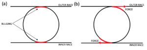
Marinov assumes that the ball-bearing motor is a heat engine rather than an electromagnetic motor [9]. The increase of ohmic resistance leads to the expansion of the ball size, which causes the contact point with inner and outer races to become hot, as shown in Figure 2.1. This leads to the expansion and elongation of the ball bearing at the contact point. When the motor is stationary, the extension of the ball will lead to the seizure of the bearing. Still, during the initial rotation, the elliptical point will generate torque in the rotation direction to maintain the movement. All the balls in electrical contact with the bearing housing are involved in the cyclic process, so the balls rotate continuously. Marinov also proposed that the engine cannot realize self-starting under the condition of perfect smoothness and geometrical perfection according to the thermal expansion theory [9]. The ball surface deviation causes the occasional spontaneous start. This theory has an obvious defect which is that the thermal effect usually has a long time constant, which means that it seems impossible for the ball to extend and contract at a medium speed. Although the theory of thermal expansion has been questioned, it cannot be ignored because there is no experimental evidence.
Plasma Discharge
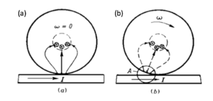
In 1973, Polivanov, Netushil and Tatarinova proposed that the Huber effect should be attributed to plasma discharge [10], a phenomenon of spark discharge on the surface of the ball and racetrack, resulting in a force sufficient to maintain rotation. According to Lenz's law, the induced current tends to flow in the opposite direction to the induced current [11]. In a magnetic field, the induced current interaction produces force, which interferes with the current symmetry and magnetic flux distribution created by point contact [11]. Figure 2.2 schematically depicts the continuous process of wheels and axles on the guide conductor track. Netushil proposed an expression of the repulsion force between the inner ring and the ball in his research [12].
F = k * I^2 (4)
Simulation
Design
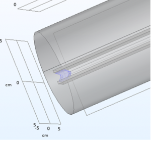
Build three related software simulations through COMSOL about electrical simulations with moving parts, including two parallel wires, a railgun, and the simplified ball-bearing motor. Then collect data from these simulations and compare it with the calculated data sample to support the physical experiment results.
Result
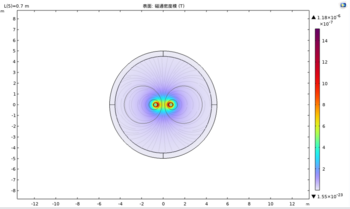
Figure 4: Two parallel wires moving apart
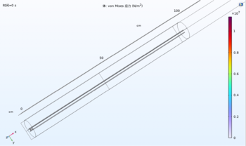
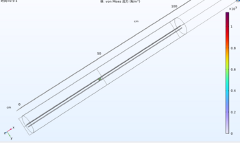
Figure 5.1: Railgun Projection Motion
Experiment Result
Design
Result
