 The
University of Adelaide
Home |
School EEE
The
University of Adelaide
Home |
School EEE 


ELEC ENG 4039A/B
FINAL YEAR HONOUR PROJECT
OPTIMISATION WLAN FOR BROADBAND ACCESS

Related Link
WLAN Background
The popularity of wireless networking has increased significantly in recent years as wireless networking provides increased mobility, flexibility, ease of use and also reduce the cost of setting up and maintenance. The most popular wireless network, nowadays, is wireless local area network (WLAN) based on IEEE802.11 standard, which is developed by the Institute of Electrical and Electronics (IEEE). WLAN is similar to LAN but allows the connections of computers without any wires, mostly using radio frequency technology. It is a part of family of standards for local and metropolitan area network as can be seen from figure 1.1.
Figure 1.1 – IEEE Standards for LAN & MAN
IEEE 802.11 standard defines the first two layer of network stack namely Physical Layer and Link Layer for a LAN with wireless connectivity. As can be seen from figure 1.1 the Link Layer is divided into two sub layers, Logical Link Control (LLC) and Medium Access Control (MAC) [1]. LLC deals with the management of errors, faults and congestion whereas MAC controls access to the shared medium which is physical layer. Thus, all IEEE 802.11 standards share the same MAC for six different types of physical layer. The most popular IEEE 802.11 standards are IEEE 802.11 b/g/a.
Figure 1.2 – IEEE802.11 a/b/g and legacy Standards for WLAN
Figure 1.2 depicts an overview of specifications of IEEE802.11 standards. Development of the original 802.11 standard (also called 802.11 legacy) began in May 1991 and was completed in June 1997. In 1999, IEEE802.11a (802.11a for short) and IEEE802.11b (802.11b for short) was ratified and most recently IEEE802.11g (802.11g for short) in 2003. These three standards are the most popular among the IEEE802.11 family in use and in academic research.
Table 1.1 - Popular IEEE802.11 standards’ Characteristics
|
Standard |
Frequency Band |
Air Interface |
Maximum Data Transfer Rate |
|
802.11 |
2.4GHz |
FHSS |
2Mbps |
|
802.11a |
5.7GHz |
OFDM |
54Mbps |
|
802.11b |
2.4GHz |
DSSS |
11Mbps |
|
802.11g |
2.4GHz |
OFDM |
54Mbps |
Table 1.1 shows the standards characteristics of IEEE 802.11 legacy and IEEE802.11a/b/g. As can be seen from the table, 802.11a operates at 5GHz band and the maximum throughput up to 54Mbps by using Orthogonal Frequency Division Multiplexing (OFDM). However, 802.11a can only operate in small coverage areas.
On the other hand, both IEEE802.11b and IEEE802.11g standards use Direct Sequence Spread Spectrum (DSSS) and operate at 2.4GHz frequency band which is an Industrial Scientific Medical (ISM) frequency band or unlicensed frequency band. There are thirteen channels available with three non overlapping channels; 3, 6 and 11. The maximum throughput of 802.11b and 802.11g are 11Mbps and 54Mbps respectively. 802.11g has adopted the OFDM technique to obtain high transmission rate at 2.4GHz frequency band.
This project focused on the 802.11b/g standards because of its widespread use, operating in the same frequency band and its compatibility which means 802.11g is backward compatible with 802.11b which is currently employed by the school of Electrical and Electronics Engineering, see section 1.3 for details.
The IEEE802.11 architecture consists of several components and services that interact to provide station mobility transparent to higher layers of network stack [3]. IEEE802.11 standard supports two network architectures namely ad hoc architecture and infrastructure architecture.
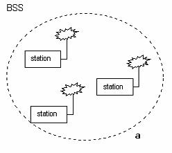
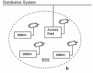
Figure 1.3 – IEEE802.11 Architecture – Ad hoc (a) and Infrastructure (b)
Ad hoc architecture is called an Independent Basic Service Set, figure 1.3 a. It includes a set of stations, which communicate directly via the wireless media in a peer to peer fashion. Ad hoc mode does not require any servers and has small coverage area.
Infrastructure architecture is an IBSS with addition of Access Point (AP) as indicated in figure 1.3 b. The AP acts as a server to relay data between stations. In infrastructure mode, the network coverage can be extended by connecting BSS together. The connections are formed by connecting APs to distribution system. This way, AP between Basic services sets can communicate together to exchange between the stations within its range. Therefore, the range of communication increased in compare with IBSS.
Wide-area WLAN
Wireless LAN was designed as a local area technology which uses for small coverage area like campus or small office. Recently, outdoor-based wireless networking has used the WLAN technology with different network deployment approaches. In doing so, the two main components of WLAN namely antenna and access point, must be carefully designed to provide maximum coverage and to minimise interference.
Wide-area WLAN can be configured as a point-to-point network, point-to-multipoint network or multipoint-to-multipoint network. All of these configurations, however, present their own challenges and none completely addresses the problems associated with deploying wide-area WLAN [4].
Point-to-point networks are the most commonly deployed among three configurations. Point-to-point systems use defined links between access points (figure1.4).Hence they can take the advantage of directional antenna which have greater gain because their energy is focused in a particular direction [4]. Consequently, link budget at both transmit and receive stations can be improved.
Figure 1.4 – Typical point-to-point WLAN design with directional antenna [4]
Useful Link for more information
Back HOME
Copyright © The University of Adelaide 2006
Copyright | Disclaimer | Privacy