 The
University of Adelaide
Home |
School EEE
The
University of Adelaide
Home |
School EEE 


ELEC ENG 4039A/B
FINAL YEAR HONOUR PROJECT
OPTIMISATION WLAN FOR BROADBAND ACCESS
Related Link
UltraWAP Hardware Hacking
UltraWAP has the ability to have a serial port added to the main board. This serial port acts as a virtual console to the running Linux firmware and hence gives the access the UltraWAP. Table1 shows the pin locations on main board and RTL8186 chipset, the pin location was found from the datasheet and board information was provided by Freenet-antenna.
Table 1 – JTAG connection on UltraWAP board
|
J1 on UltraWAP |
RTL8186 |
Symbol |
Description |
|
PIN 1 |
PIN 51 |
DVDD33 |
CPU +3.3V (Not in Used) |
|
PIN 2 |
PIN 33 |
GPAPIN[6] |
RxD (JTAG_TDI) |
|
PIN 3 |
PIN 35 |
DGND33 |
CPU 3.3 GND |
|
PIN 4 |
PIN 116 |
GPAPIN[9] |
TxD( JTAG_TDO) |
The serial port connection could be established by using Jumper 1 on the main board as can be seen from figure 1. Having said the main board was not required to have hardware modification. The serial console was built base on the schematic in figure 2.
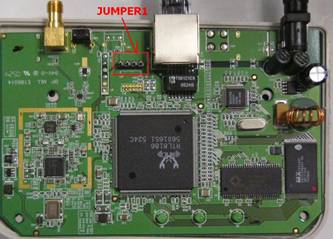
Figure A1 – UltraWAP main board which J1 is highlighted
Before connecting the serial console to Jumper 1 on the main board, it is essential to ensure the port is always connected to no higher than 3.3V or else the chip may be burnt.
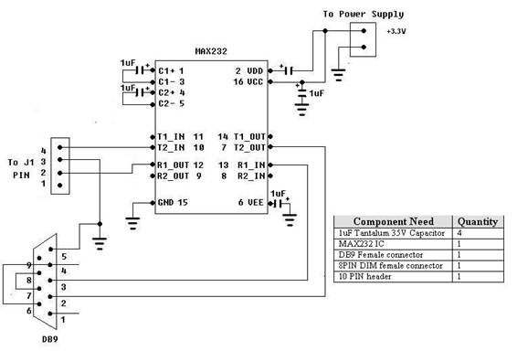
Figure 2 – Serial Console Schematic
Shell Access to UltraWAP
The serial console was connected to the main board to gain the shell access to UltraWAP. In doing so, follow the below steps:
- Connect serial port on the serial console to the serial port on the computer.
- Connect 10- pin header on the serial console to 4-pin jumper 1 on the main board.
- At PC, run minicom and must set the baud rate to 38400, 8N1 and no flow control. The settings based on the code analysis from the 1st stage boot loader.
Upon powering up the UltraWAP, if everything was done correctly, the boot messages of UltraWAP would appear as indicated in figure 3. It showed that the boot loader first loaded the firmware image and then entered the second boot loader before decompressing the kernel and other initialisations. This start up run for a few seconds and the login prompt would appear. Thus, the shell access was protected by username and password. According to the information given by Rob Clark, Freenet Antenna, the username is prompt and the password is Ctrl+C . However, experiments showed that the username could be any characters that the user typed in.
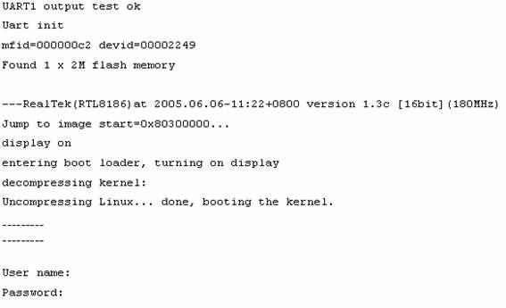
Figure 3 – Output of Shell Access to UltraWAP
After logging in, the Linux system could be examined and analysed. The current kernel version running on UltraWAP was 2.4.18. Also, there were few important files that must be understood and studied to gain a better understanding on UltraWAP system.
If UltraWAP was power up and ESC key was hit quickly enough, the first stage boot loader would stop and the boot messages same as figure 4 would be shown. this stage allows the firmware to be uploaded and allow the users to flash its memory and jump to specific memory address.
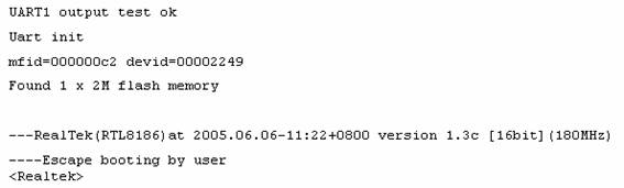
Figure 4 – First stage boot loader to upload, flash and jump to memory address
More information
Copyright © The University of Adelaide 2006
Copyright | Disclaimer | Privacy