Advantest
Contents
Laser Safety
The unit operates in the eye-safe part of the spectrum around 1.5 \mu~m. However, the peak power available from the port of the analysis unit is 27~W which may be hazardous. This optical energy is only accessible when the fiber optic connector is disconnected and the optic ports are exposed. Care should be exercised that fiber optic connectors are not disconnected while energized. In addition to posing a slight eye hazard, this may also damage the equipment.
Presentation
Advantest THz system with a 7 THz bandwidth utiliziong the Cherenkov transmitter
Hardware Manual
This manual describes the hardware configuration, functions, tasks to be performed before starting measurement, and notes on use of the System. This is to be used in conjunction with the System Software Operation Manual.
Software Manuals
System Software Manual This manual describes the system software for spectroscopic measurements and analyses.
API manual This manual describes automatic control measurement options and the Remote Application Programming Interfaces (APIs).
VB LIB manual This manual describes the Visual Basic (VB) arithmetic library suuplied with the Advantest
Quantitative Analysis This manual describes the quantitative analysis software supplied with the Advantest. This uses multiple spectra to provide an estimate of the quantity of a component.
Using The Advantest System Software
1.Click on Remote Desktop Connection to log on the internal computer inside the system. The user name is “advantest” and password is “advantest”.
2.Once clicked [OK], the system will execute the following commands. Until the command “Master SeedLaser Tec completed” is done. Then can start the system software.
3.Double click the TAS7x00 icon on the desktop to open the navigation window.
The navigation window has 4 icons; Measure, Setup, Analysis and Exit.
4.Selecting Terahertz Source and Detector Modules, and Generating Optical Pulses by clicking the [Setup] button in the Navigation window to open the System Setup window below.
5.Select a combination of terahertz source and detector module connections. (Master side: Terahertz source module, Slave side: Terahertz detector module)
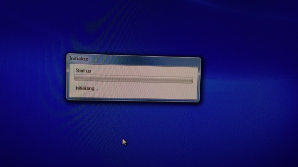
6.For our system setup, select CH2:Master. CH2: Slave. Then click the [Initialize] button to generate optical pulses for adjusting the optical system. The THz Tuning & Monitor window then opens.
Adjusting Optical System
Perform the following procedure:
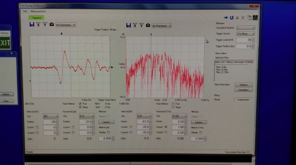
1) Set THz Wave for Trigger Source and select a small value for Cumulated Number in the condition setting area, and then click the [Repeat Measurement] button on the toolbar. The waveforms are then displayed in the monitor status similar to an oscilloscope.
2) If waveforms are not displayed, adjust Trigger Level and Trigger Position. To adjust the display position and range of the waveforms, change the parameter values under each graph. If expected waveforms still cannot be obtained even after adjusting these parameters, alignment of the optical system is required. Align the optical system while observing the waveforms.
3) When expected waveforms have been obtained, click the [Stop Measurement] button on the toolbar to terminate the measurement.
4) To check the stability of the waveforms, specify a value used for the actual measurement for Cumulated Number and click the [Single Measurement] button on the toolbar.
Selecting Delay Fiber
Perform the following procedure:
1) Click the [Fiber Select] button on the toolbar in the THz Tuning & Monitor window. The selected delay fiber is than displayed in the Selected Fiber field.
2) The currently connected 0.5-m delay fiber must be replaced with the selected delay fiber.
3) Click the [Replace] button to safely prepare the system. When the following confirmation message is displayed, click the [OK] button. Generation of optical pulses for adjusting the optical system then stops.
4) Confirm that the PUMP lamp on the front of the measurement unit extinguishes, and then connect the fibers listed in the field. E.g. 0.5m + 0.25m + 0.125m
5) When the replacement of the fiber is complete, click the [Completion] button. When the following confirmation message is displayed, click the [OK] button. Generation of optical pulses for adjusting the optical system starts again.
6) After optical pulses for adjusting the optical system is generated, the following message is displayed. Click the [OK] button.
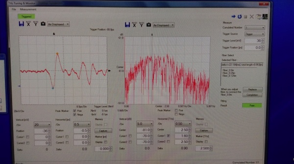
7) Click the [Fitting Trigger] button on the toolbar in the THz Tuning & Monitor window.
8) When optimization succeeds, "Pass" is displayed in the Fitting Result area. When optimization fails, "Fail" is displayed. If "Fail" is displayed, the optical system must to be readjusted.
Measure
1) Close the Thz Tuning & Monitor window and then click the [Measure] button in the Navigation window to display the following Confirmation dialog box.
2) The unit takes approximately 15 minutes to warm up and initialize. Do not click on any other icons during this time.
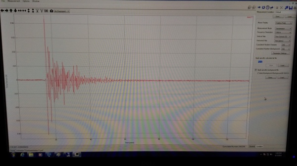
3) When the Measurement window opens,you can set the measurement conditions.Click the [Run] button to measure the background. A background waveform is then displayed in the Measurement window.
How to use the Air Compressor
Please look at SOP and RA before using this equipment.
1) Close the stop valve and place the operation switch in ON position.
2) Compressor starts and air tank internal pressure rises.
3) The pressure rises up to the cut-out pressure of 0.8Mpa, the compressor will stop.
4) Open the stop valve to half turn and air tank internal pressure drops down to 0.5MPa.
5) Don’t turn the stop value more than ¾ turn otherwise the air tank internal pressure will drop below 0.5MPa and can’t be kept stable.
7) Check the air compressor for abnormal vibration or noise.
8) Never touch the motor when it is running or has just stopped as the motor is hot.
See Also


